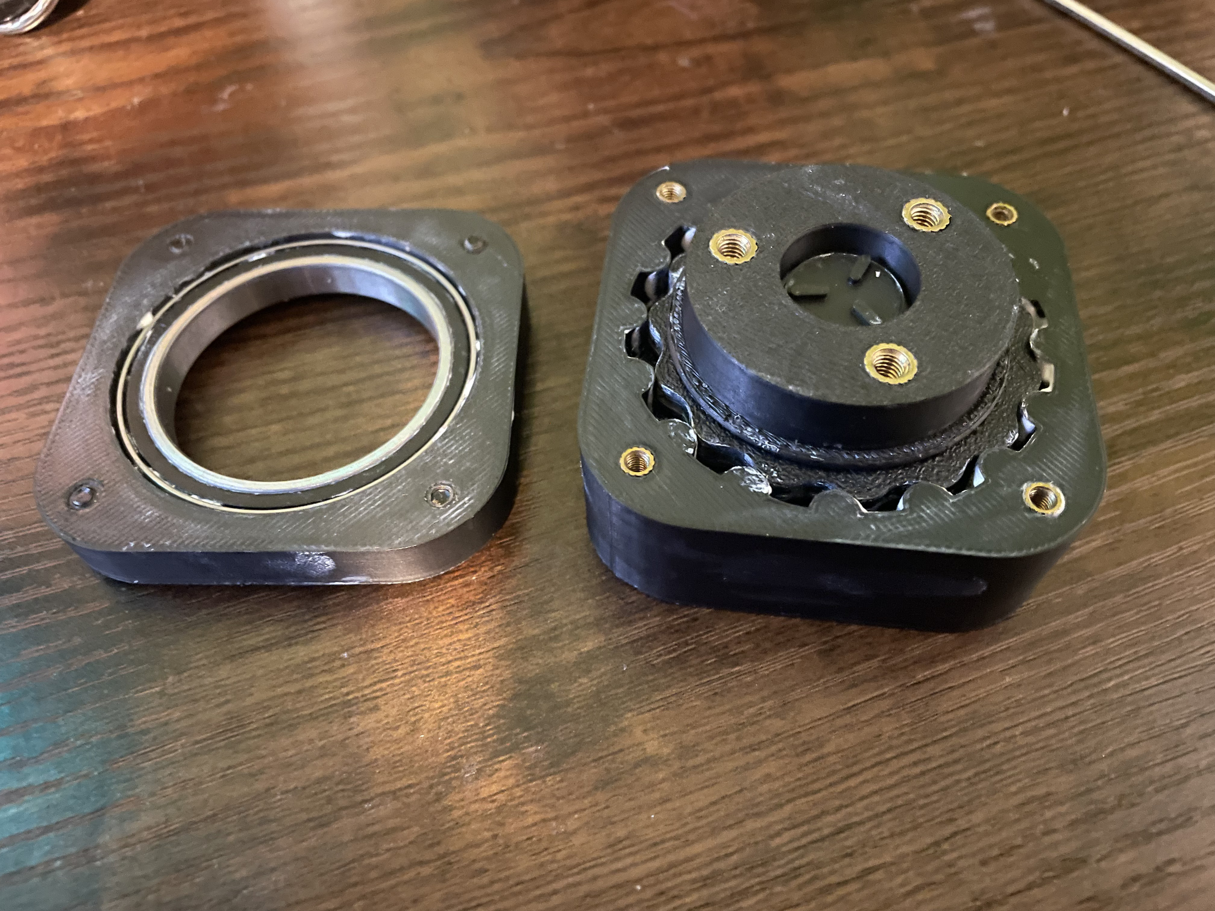
I’ve Made Cycloidal Drives
I wanted a cycloidal drive. I saw that I could download some STL’s from the internet. I decided not to, mostly because I was fascinated by them and wanted to learn more. What ensued was a surprisingly insightful journey where I found how limiting FDM printing can be and how much I love trying to get parts tiny.
Mathematical Modeling
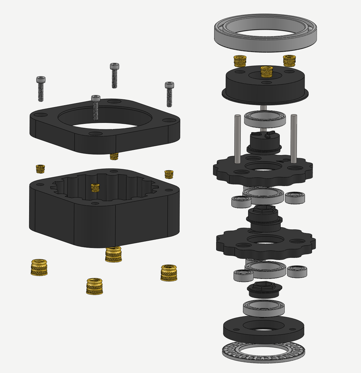
Modelled in SolidWorks
The full assembly was made in SolidWorks, with components like the bearings taken from McMaster-Carr. Note the thrust bearing on the bottom, which I used after realizing axial load could be supported by the motor itself rather than requiring a dedicated full bearing at the input
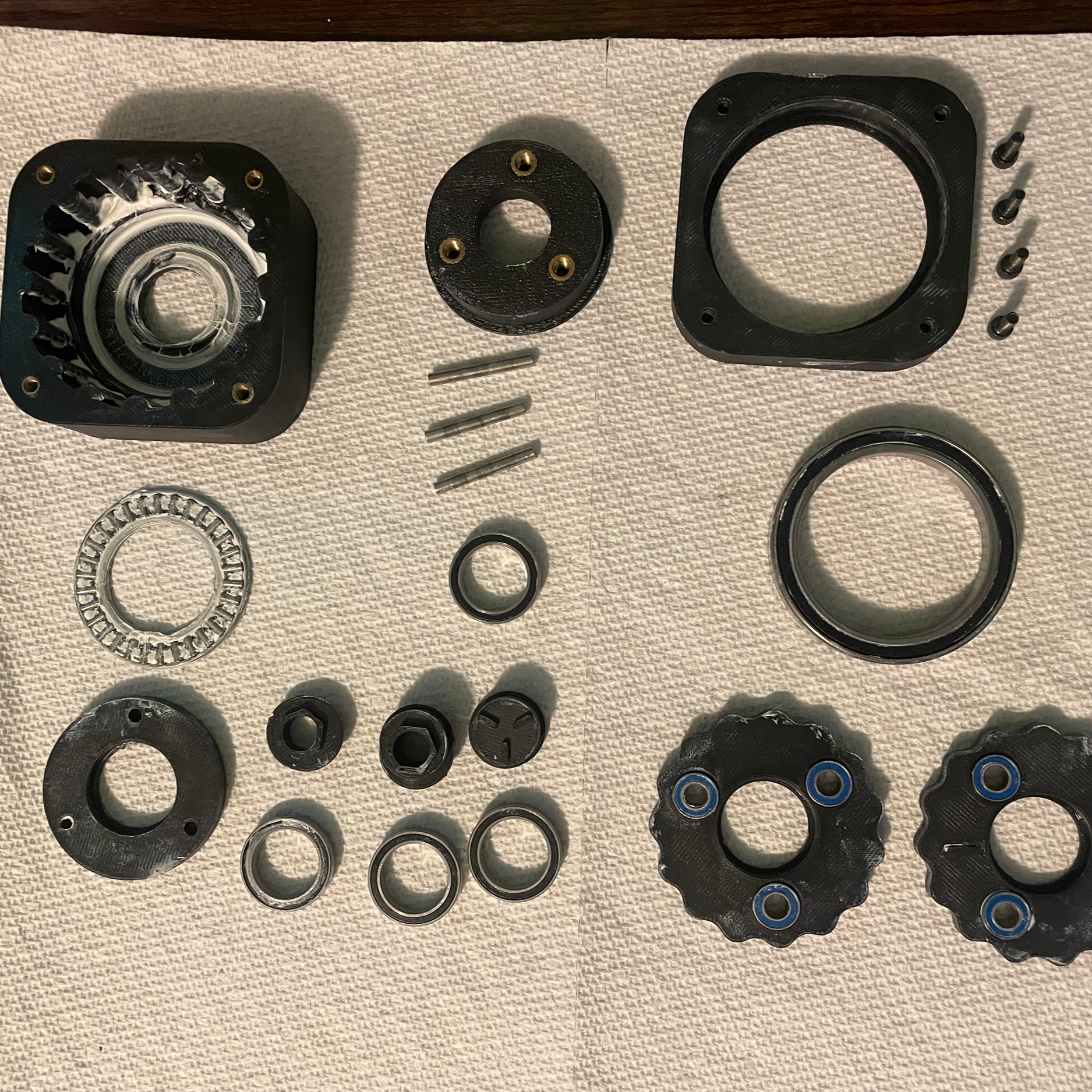
Disassembled Parts
Here is a collection of the components of the cycloidal mechanism. My goal for this project was to make the drive as small as possible. I ended up reaching the limits of what I believe is possible with an FDM printer, at least while still achieving a smooth transfer of power.
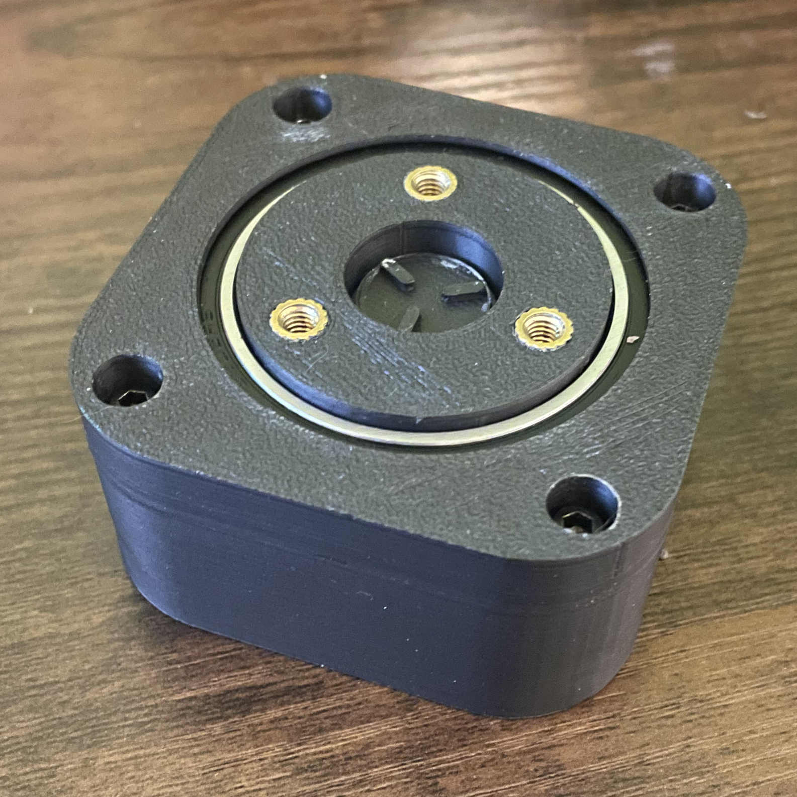
Compact Assembly
The overall projection of the cycloidal drive was approximately 32mm, with the main limiting factors being the thickness of the bearings. The silhouette of the drive fits within a standard NEMA 23 motor, although it could be made smaller if alternative printing methods like SLA printing was available.